Choosing a quiet fan with jet physics
Working draft. The physics below is real, and the fan figures come from manufacturers’ catalogues and independent reviews (ETM Testmagazin, mybest, Expert Reviews, Trusted Reviews, TechGearLab). None of it is my own measurement yet, and the long-range numbers are model extrapolations, not data. I would rather publish the method early than polish it in private.
I want a fan that moves air across a room without sounding like one. The marketing numbers (CFM, dB at some unspecified distance) do not say much about how it will feel three metres away. A cleaner way to think about it is to treat the fan outlet as a turbulent jet and ask what physics sets how far it carries.
A short physics lesson: the equations air obeys
Everything below rests on one set of equations, so it is worth meeting them properly. Air in a room moves slowly compared with the speed of sound, so we can treat it as incompressible, and then its motion is governed by the Navier–Stokes equations:
∂u/∂t + (u·∇)u = −∇p/ρ + ν∇²u + f, ∇·u = 0
Read it as Newton’s second law for a small parcel of air, per unit mass. On the left is how the parcel’s velocity u changes: partly with time, and partly because it is carried into a region where the flow is different (the (u·∇)u term). On the right are the forces that cause that change: pressure differences (−∇p/ρ), viscous friction (ν∇²u), and any body force f, such as a fan pushing or cold air sinking. The second equation says no air is created or destroyed: whatever flows into a region flows out.
Which of those terms actually matters? Scale everything by a typical speed U and size L, and the equation becomes
∂u*/∂t* + (u*·∇)u = −∇p + (1/Re)·∇²u
so the only thing that decides the kind of flow is a single number in front of the viscous term.
Here is Re for the flows that matter in our house:
Reynolds numbers around the house
At high Re you might think viscosity simply drops out. It does not, quite. Turbulence passes energy from big eddies to smaller ones (the energy cascade) until the eddies are so small that viscosity can finally turn their motion into heat.
The practical consequence is lovely: once a jet is turbulent, its spreading is set by its own eddies, not by the air’s viscosity, so the jet’s shape stops depending on Re at all. Here is Re for a 12 cm outlet at various speeds, just to show how quickly we leave the laminar world:
Jet Reynolds number for a 12 cm outlet
One more force matters in a house with an air conditioner: cold air is heavier than warm air.
Archimedes number for air 8 °C colder than the room, over 1 m
Momentum wins, viscosity barely matters
For a turbulent round jet, the far field is self-similar and independent of Re. The centreline speed falls as
u_c(x) ≈ B·d·U / x, with B ≈ 6.2
so what matters is the product of outlet diameter and outlet speed, i.e. the momentum flux.
Centreline speed vs distance (12 cm outlet)
The trade that makes a fan quiet
Thrust (momentum flux) is T = ρ·(π/4)·d²·U². Hold it fixed and the throw, which scales as d·U, does not change with diameter at all: a bigger, slower outlet delivers the same punch down the room. Noise, however, rises steeply with speed. Using a rough U⁶ scaling for broadband fan and jet noise as a stand-in:
Same push (0.5 N), different outlet diameters
Here is the same idea as something you can play with. The particle jet is the far-field model above, with the spreading rate of a real turbulent round jet. Hold the thrust constant and drag the diameter: the yellow line (where the breeze drops to a just-noticeable 0.5 m/s) barely moves, while the noise figure falls away.
Try it: outlet size vs outlet speed
- Throw to 0.5 m/s
- Thrust
- Airflow
- Reynolds number
- Noise vs reference
So the shopping heuristic is: maximise outlet area for the thrust you need, then check the motor and blades are not adding their own whine.
The real question: getting the cold air down the hall
The free-jet picture says what a fan can do in open air. Our actual problem is a house: one split system on the dining room’s north wall, and bedrooms down a hallway that the cold air never seems to reach. So I took the floor plan from the digital twin of the house, with its walls, doorways, kitchen joinery and the default furniture layout, and ran a 2D airflow simulation on it, right here in the page.
Live: the split system and a Dreo fan, on the actual floor plan
What it shows, averaged over the second half of 45 simulated seconds (AC at 3.5 m/s, fan at 4.5 m/s):
| Where | AC only | Dreo through the kitchen gap | Dreo around the retreat |
|---|---|---|---|
| Dining | 0.45 m/s | 0.76 m/s | 0.62 m/s |
| Living | 0.13 m/s | 0.52 m/s | 0.38 m/s |
| Retreat | 0.005 m/s | 0.76 m/s | 0.79 m/s |
| Hall | 0.003 m/s | 0.71 m/s | 0.46 m/s |
| Bedrooms | about 0 | about 0.01 | about 0.01 |
Three things jump out.
- On its own, the split system’s air stays in the dining and living room. The jet hits the floor-to-ceiling obstacles (fridge, island, sofa) and curls back on itself. The hall is effectively dead air.
- One fan in the right place changes that completely. Pointed south through the gap east of the kitchen, it sets up a loop: down through the gap, west along the hall, back up through the retreat into the dining room, where the AC tops it up again. The retreat route works too, but more of its push is spent in the retreat itself.
- Bedrooms are dead ends. Even with every door open, almost nothing flows through a bedroom, because there is nowhere for the air to come out. A second fan in the hall aimed straight into the Bed 2 doorway lifts that room’s average from 0.01 to 0.05 m/s, but it is a local swirl of hall air at the door rather than a supply of cooled air, and it partly fights the first fan. Getting conditioned air into a bedroom needs a through path (a door undercut or transfer grille plus a fan pushing in) or a head in the room. Try it yourself: choose “Place your own fan”, then press in the hall and drag towards a bedroom door.
This is a 2D, depth-averaged slice, so it is honest about where air can go but not about the ceiling: a real split-system jet hugs the ceiling (the Coandă effect), and cold air sinks as it slows. Tall things like the fridge block most of the slice; low things like beds and the dining table only add drag. The solver is a lattice Boltzmann method with a Smagorinsky turbulence model, running in a Web Worker in your browser. The return air the split system draws in from the ceiling is modelled as a gentle sink around the head.
Into the bedrooms: the same house in 3D
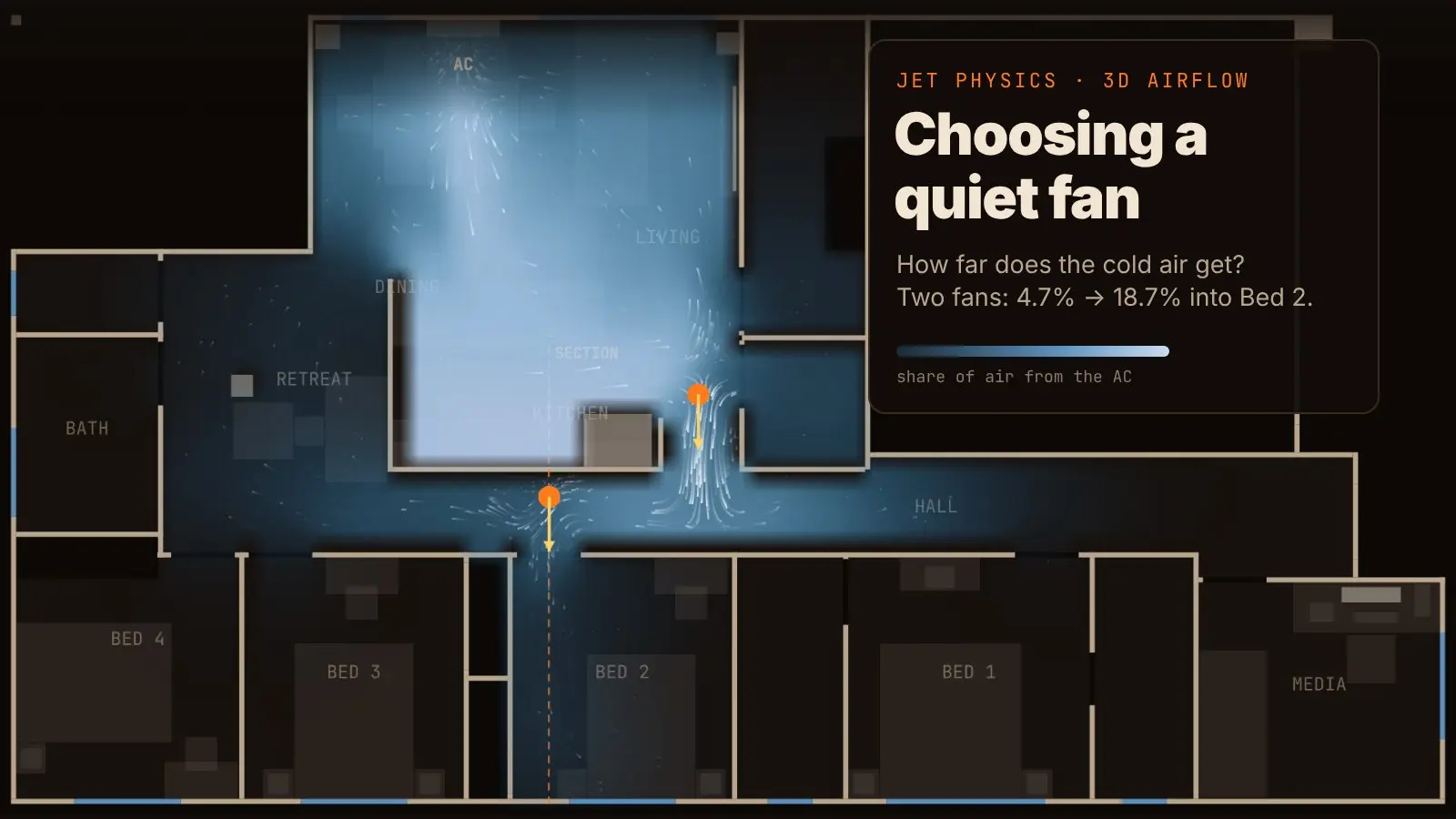
The 2D slice can’t answer the question I actually care about: how much of the cooled air ends up in a bedroom. A doorway is a 3D thing. Air can come in over the top and leave along the floor, or the other way round, and a split system’s jet runs along the ceiling. So here is the same house again, this time as a full 3D simulation: every wall, door head, the fridge and its bulkhead, the furniture, and a 2.59 m ceiling, with the AC as a real slot of air on the north wall of the dining room.
Live in 3D: getting the split system's air into the bedrooms
AC air: settling
The top view is a plan cut through the occupied zone. Below it is a vertical section through the bedroom door you pick, so you can watch air cross the doorway at different heights. Colour by “AC air” to see where air that has passed through the split system has got to. Each room card shows its share, its average speed, and how many litres a second go through its door.
The solver is a D3Q19 lattice Boltzmann model with the same Smagorinsky turbulence closure, on about 31,000 air cells of 22 cm. A phone gets a coarser grid of 26 cm. Fans are actuator discs. A closed door is a solid leaf with a 12 mm undercut. The AC air is tracked as a dye, and can optionally be treated as 8 °C colder than the room so it sinks.
Two minutes of simulated time, AC at 300 L/s with the louvre angled 15° down, cold air on, fans at 4.5 m/s from a 25 cm outlet 0.9 m off the floor. The figures are the share of air in the occupied zone (0.1 to 1.8 m) that has been through the AC:
| Room | AC only | Hall fan into Bed 2 | Two fans (kitchen gap + hall) | Hall fan, doors shut |
|---|---|---|---|---|
| Dining | 43% | 42% | 36% | 44% |
| Living | 48% | 48% | 43% | 49% |
| Hall | 19% | 19% | 27% | 21% |
| Bed 2 | 4.7% | 9.4% | 18.7% | 0.2% |
| Bed 1 | 1.5% | 1.7% | 4.8% | 0.3% |
| Bed 3 | 1.4% | 0.7% | 1.8% | 0.1% |
| Bed 4 | 1.9% | 1.3% | 1.6% | 0.1% |
| Bed 2 doorway | 59 L/s each way | 674 L/s | 671 L/s | about 1 L/s |
What I take from it:
-
The AC jet does hug the ceiling. With the louvre level, the fastest air 2 to 4 m out is in the top cell, at 2.5 m. Angle the louvre 15° down and the cold air starts to drop by about 4 m out. This is the Coandă effect, which the 2D slice could not show.
-
With the AC alone, cold air pours into the bedrooms along the floor. Each open doorway trades about 50 L/s: cool hall air flows in low and warm room air flows out high. It is a slow, buoyancy-driven exchange, and two minutes in the bedrooms are still under 2% AC air.
-
One hall fan aimed at a doorway doubles that room’s share. It pushes about 670 L/s through the middle of the doorway, and the air returns along the floor and under the door head. But it can only move the hall air it has, and the hall is only 19% AC air.
-
A second fan at the kitchen gap doubles it again. Pushing the dining room’s air down the hall first makes the hall fan’s air colder. Bed 2 goes from 4.7% to 18.7% in two minutes. The other bedrooms barely change, so this is a strategy for one room at a time.
-
Shut the door and the fan does nothing for that room. A 12 mm undercut passes about 1 L/s and there is no path back out, so the room is sealed off from the AC.
Honest limits. The grid is coarse: there are only two cells above a door head, and a fan disc is a single cell, so its total push is right but the near field is crude. The ceiling is modelled as slip, because at this resolution a no-slip ceiling would not let the jet attach. “AC air” counts anything that has passed through the AC since the start, with no heat gained from the rooms, so it is a measure of mixing, not temperature. It is a model to rank options against each other, not to predict the thermostat.
Which fan? Separating data from extrapolation
I started with Dreo’s shortlist and ended up reading every independent fan test I could find: 52 fans, 108 measurement rows. Most are useless for this question, and it is worth being clear about why before looking at any chart.
The other trap is that the same fan has different names in different tests, and the tests cannot be mixed. Every fan on the charts below is labelled the way its tester labelled it, with the closest match in brackets where I had to guess. Dreo numbers its models in families: 3xx (the 353), 5xx (the 512, and the 513S, 508S and 502S that ETM tested) and 7xx (the 704S, 714S and 765S). The 5xx fans share a 9 in rotor, so the 513S results are the best stand-in for my 512, but the 512 itself has never been measured.
The other trap is distance. Most reviewers measure air speed at 1 m, which tells you about the outlet, not the throw. Only one tester measured at hallway distance: mybest, at 6.1 m (20 ft), with the strongest reading taken from a grid of 36 points and noise at 1.5 m.
At hallway distance: 6.1 m
Air speed 6.1 m away vs noise, every fan at full power (mybest)
This supports what I suspected about the big-brand circulators. A Vornado 7803 at full power gets 2.44 m/s to the far end of a 6 m room and makes 62.5 dB doing it; the Dreo CF714S gets 2.75 m/s for 54.9 dB. Eight decibels is the difference between “fan noise” and “a fan you can sleep next to”. Most of Vornado’s range here uses AC motors (the 460, 560, 630, 633, 660, 683, 7503, 7803); their DC models (533DC, 633DC, 683DC, 5303DC, 6303DC) cost more and were not in this test.
How much speed survives the trip
mybest measured eleven fans at both 1.5 m and 6.1 m with the same grid method, which gives something rare: how much of a fan’s speed is still there at the end of a hallway, which is what a hallway fan is for.
Air speed left at 6.1 m, as a share of the speed at 1.5 m (mybest)
- Lasko 3300 4.5 → 2.2 m/s 50%
- Dreo Portable Pedestal 5.0 → 2.5 m/s (513S-class?) 49%
- Pelonis box 3.2 → 1.5 m/s 47%
- Vornado 660 4.9 → 2.2 m/s 45%
- Vornado 7803 5.6 → 2.4 m/s 43%
- Dyson Pure Cool TP01 3.0 → 1.3 m/s 42%
- Lasko 1827 3.8 → 1.5 m/s 41%
- Pelonis FS40 DC 4.2 → 1.6 m/s 40%
- Lasko Wind Curve tower 3.2 → 1.2 m/s 37%
- Pelonis PFS40 3.9 → 1.2 m/s 32%
a fully developed free jet that started at the fan face would keep about 25% (1.5 m ÷ 6.1 m)
Up close: the quiet envelope at 1 m
At 1 m there is much more data, including every setting of three Dreo circulators (ETM Testmagazin) and spot readings from Expert Reviews. Each line is one fan walking through its speed settings.
Air speed at 1 m vs noise at 1 m, setting by setting
A few things this teaches:
- Noise climbs much faster than air speed. Fitting the 513S’s settings gives noise rising about 43 dB per tenfold increase in speed, so sound power goes roughly as speed to the fourth power (the 502S fits closer to the fifth). Textbook fan-noise scaling says 5 to 6. The practical rule: running a bigger fan slower beats running a small fan flat out.
- Power is cheap, noise is not. The 513S draws 2.9 W at speed 1 and 25 W at speed 8: about 2 cents a day at the bottom and 18 cents flat out, around the clock. The cost you pay for air is decibels, not electricity.
- Fans are curves, not points. A spec sheet gives one number for the top speed; what matters at night is the bottom-left of each curve.
Dreo 513S: noise vs power draw (ETM, measured)
353 vs 512: the two Dreos you can actually buy here
These are the two models sold locally (A$159.99 and A$189.99 on amazon.com.au), and I now own a 512. Neither has an independent measurement, so this is the jet model run on Dreo’s own listed figures. Both list the same 25 ft/s (7.62 m/s) outlet speed and the same 20 dB at the lowest setting. What differs is size: the 512 has a 9 in (229 mm) blade against the 353’s 8 in (203 mm), and a higher airflow claim (1,100 against 1,000 CFM). At the same exit speed the bigger outlet moves more air, so it carries more momentum, and in the far field the centreline speed goes as outlet speed times outlet diameter. By how much depends on what you take the outlet to be:
| Dreo 353 | Dreo 512 | 512 vs 353 | |
|---|---|---|---|
| Blade diameter | 203 mm | 229 mm | +13% |
| Claimed exit speed | 7.62 m/s | 7.62 m/s | same |
| Claimed airflow | 1000 CFM | 1100 CFM | +10% |
| Push, treating the rotor as the outlet (ρ·A·U²) | 2.3 N | 2.9 N | +27% |
| Push, from the catalogue airflow (ρ·Q·U) | 4.3 N | 4.7 N | +10% |
| Speed at the far end of a room (goes as the square root of the push) | +5% to +13% | ||
| Noise to match the 353’s far-field push (U⁶ rule) | 1.24 to 3.14 dB quieter |
So the 512 gives a fifth to a quarter more push if you trust the rotor size, or a tenth more if you trust the catalogue airflow (which probably includes air the jet drags along). That is where the “about 20%” I remembered lives: it is the push, not the speed down the hall, because speed only grows as the square root of push. At 7 m that is roughly 1.37 m/s for the 353 against 1.55 m/s for the 512 on the rotor estimate: the 512 never falls behind and leads by about the amount in the table.
The quieter part is weaker. Dreo claims the same 20 dB minimum for both, and I could not find any test that measures either. What the model says is that, because the 512’s outlet is bigger, it can make the same push at a lower exit speed, and with noise rising as speed to the sixth power that is worth about 1.24 to 3.14 dB. That is audible side by side but small, nowhere near a fifth.
A correction to the earlier draft. It claimed the 512 carried about 24% more far-field speed than the 353 and about 2% more momentum. Those came from ChatGPT’s inputs (a 7 in rotor and 7.92 m/s for the 353). Dreo’s own spec lists an 8 in blade and 7.62 m/s, which is what the table above uses, so the far-field gap shrinks to +5% to +13% while the push gap grows to +10% to +27%.
353 vs 512: modelled centreline speed (not measured)
A word of caution on models like this: one French review reportedly measured a 765S dropping from 4.8 m/s at 1 m to 0.3 m/s at 7 m, far below what any free-jet formula predicts. Oscillation, aim and room recirculation all eat throw. That is exactly why the hallway needs measuring, and why the house simulation further up matters more than the jet formula.
Prices, and a warning
Delivered in Australia in October 2026, the picture is lopsided. The 353 (A$159.99) and 512 (A$189.99) are sold locally on amazon.com.au. Vornado’s AC circulators are A$150 to A$250 and the DC ones A$200 to A$350. The Dreo models with the best measured data are not sold here at all: a 765S comes to roughly A$400 or more delivered from amazon.com, which was the only store that would ship it, and a positioning-based Dreo “Intelligent Fan” (most likely the 707S) appeared on amazon.com.au at A$389.60, only after I asked Dreo about Australian availability:
Watch out for fake “Dreo Australia” stores. While shopping I found several sites pretending to be Dreo’s Australian store; I reported them and Dreo had some taken down. Dreo’s own brand-protection page warns about the
dreo-[country].compattern, and it lists no official Australian shop. If a site offers Dreo fans in Australian dollars at a discount, assume it is a scam and buy through a marketplace you trust.
Where that leaves me. The measured data favours DC-motor circulators with big rotors run slowly, and on the evidence the Dreo 5xx and 7xx families sit on the lab-measured frontier, and the Meaco Sefte Pro 10 is a promising single reading worth checking. The two fans I can buy cheaply here (353 and 512) are unmeasured: the 512 should push 10 to 27% harder than the 353 for about the same noise, but that is a model, so the next step is obvious: measure my 512 in the actual hallway, at 1, 3, 5 and 7 m, against a sound meter, and put it on these charts.
What is next
- Measure the candidate Dreo’s outlet area and real exit speed with an anemometer.
- Replace the placeholder
Band theU⁶rule with measured decay and a dB(A) reading at 1 m, 3 m. - Check the 3D simulation against reality: a cheap thermometer in Bed 2 with one fan, then two.
- Put the 704S/714S on the noise chart: measure air speed at 1, 3 and 7 m and dBA per setting, with the meter in the same place for every fan.
- Measure air speed in the hall with the AC alone and with the fan in each spot, and put the measurements next to the simulation.